Quick Links:
Zen and Art Home
Disclaimer
Errata Parts
and Parts Vendors Truck Sales
Service
and Repairs
Engine Fuel Hydraulics Radiator and
Cooling Air
System Brakes
Wheels Tires Electrical
and Batteries
Transmission
Clutch Axles Hubs Body Air Conditioning Tools Safety
Transmission
I was actually very lucky with my transmission during the time that I owned my mog. It turned out that the transmission had just been fully replaced prior to my taking ownership of it. The reason was that the previous owner failed to heed the warnings in the Owner's Manual about flat-towing the truck. Some failure prevented the truck from running, so he had it towed. Many miles and at a speed that was higher than allowable. Mog transmissions on the SBUs have a special protocol for flat towing. It has to be in the correct gear, with the transmission in the state to allow the splashing of fluid on the gears. Otherwise, you starve the gears for lubrication and they will fry. That is exactly what happened resulting in new transmission. These are not cheap; the last time I checked they were on the order of $10K, so please read your manual if you have to flat tow your truck. Oh, and lest I forget THERE ARE SPEED RESTRICTIONS ON FLAT TOWING. The pump that lubricates the inside of the transmission is driven by the input shaft. When the input shaft is not turning, there is no pressurized lubrication, thus requiring slow towing speeds. As my nerd buddies say "RTFM" - read the fucking manual.
The shop manual calls for 10W engine oil in the transmission. These days, this sort of oil is easily available in Walmart at reasonable prices. The smaller cars are now using lighter viscosity oils and I have seen 0W-10W multi-viscosity oil on the shelf. The thicker the oil, the harder the tranny shifts. On mogs with the 8 speed transmission the 4-5 shift is air assisted. When you change gates from 3-4 to 5-6 you will hear a "thunk" which is the air pressure disengaging the pre-reducer gear in the transmission. The mog is a "straight 8" shift pattern, but in reality it is a 4 speed with the pre-reducer used for the lower 4 gears. The thing to note is that if you don't have air pressure, you cannot make this shift. Of course, as discussed in the Air System section of this set of pages, there are other problems to worry about if you don't have air pressure and shifting is really low on that list. When it is cold, the transmission will shift harder than when it is warm. You cannot shift the transmission fast like a car, it must be slow shifted until it warms up. Even then, it is slower than a car. The 4-5 transition is the most likely to grind when cold. You can experiment with various viscosities of oil to see what works best for you. Thicker oil works better when warm, but grinds when cold. Thinner oil does the opposite.
As an (expensive) experiment some time ago, I put in Amsoil "Severe Gear" oil in the tranny. It helped the shifting when cold, but made it more prone to grinding when hot. The stock recommendation of 10W engine oil is a good compromise. And, now that there are light multi-vis engine oils out there at reasonable prices, it would be worth a try.
You should change the oil every year and after any deep water crossings. When you change the oil, check the plug for debris (it has a magnet). If you are seeing debris on the plug you need to raise your awareness. Light particles are to be expected. Chunks are not.
There are multiple drain plugs on the tranny, one for each chamber. Drain them all. I don't like the use of teflon tape to aid in sealing. We broke a case using the tape. I much prefer the can with the teflon goop. It does not stress the castings (the plugs are tapered, so they are a round wedge and can exert tremendous forces as you tighten the plug). Most auto parts stores have the teflon in the can. If you elect to use the tape, don't get heavy handed as you may get a surprise.
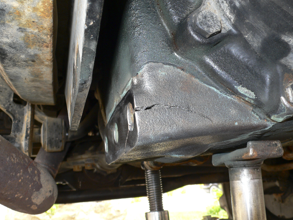
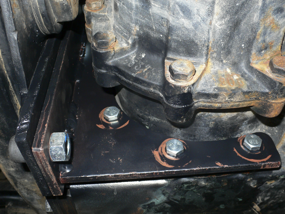
Not everthing that
can go wrong with the transmission is internal to the
case. See the photos below.
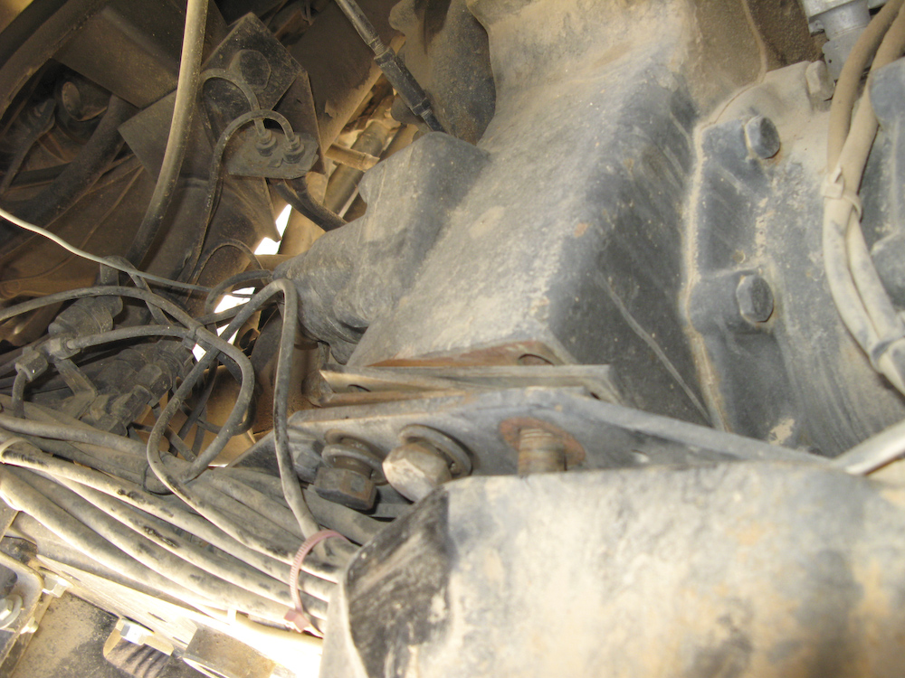
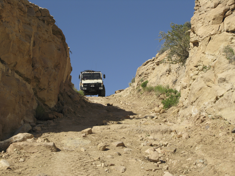
We
were ascending a steep grade in a remote area of the Grand
Staircase N.M. About 1/2 way up the grade, something
snapped and the truck started making a terrible noise. Since
we were at the crux and the steepest part, I really had no
choice but to continue on at the slowest possible pace. Once
we reached a nearly level landing zone at the top, I stopped
to determine what was wrong. I could not get the
transmission to shift and the throw on the levers was such
that I could not get the shifter in the forward position.
Furthermore, I could not get the truck out of compound low!!
It was almost as if the transmission had moved on its
mounts. I looked and looked, but could not see what was
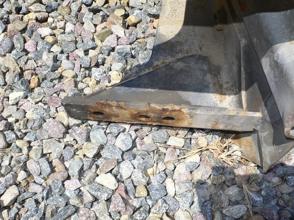
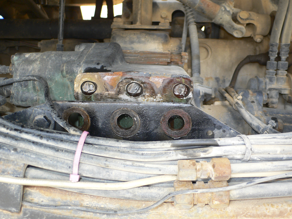
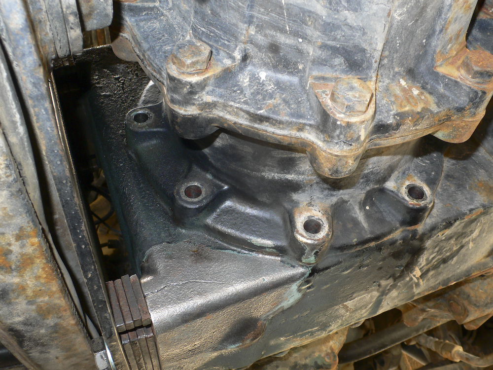
wrong. Finally, I removed the spare tire that allowed me a
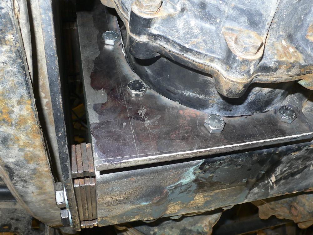
better inspection point. The photo above is what I saw. (At
Least) 3 of the 6 bolts that hold the transmission on the
driver's side had sheared off allowing the transmission to
float around. This accounted for the inability to position
the shift levers correctly. Note that the transmission has
moved forward by about an inch and you can see the shim
plates just hanging there. Succinctly put, we were deeply
screwed, through and through. The failure happened at about
1300 hours. The outside temperature was perhaps a 100
degrees and shade was nowhere to be found. In the
photo above, you can see the broken bolts. You can
also see the shims that sit between the frame rail and the
transmission. One of these shims fell out, likely
after the bolts broke. I am guessing that the hundreds
of miles of washboarded roads that we recently traveled
worked things loose. Also, I guess that when the
transmission was replaced before i got the truck, the bolts
were not sufficiently tight nor put in with thread locker.
These are big, grade 8 bolts (metric 12.9). The heads are 24 mm. To make things more fun, the ends of the bolts were left in the transmission case and at least one corner of the case was cracked.
Kathleen and I spent a very long time discussing our next steps. It was clear that I would not be able to repair the damage. I had an air drill and drill bits, but no screw extractor. Even if I got the bolts out, I did not have spares. The transmission - transfer case - reducer box on the mog is huge. I do not know the exact weight, but my guess is between 1,000 and 1,500 pounds. Bailing wire is not going to fix this issue, that is for sure. At this point, we were about 50 miles on the dirt. Due to our location, the high canyon walls, and the heat, walking out was out of the question. We tried our 2 meter radio, but it is line of sight and we could not hit the repeater on Navajo Mountain. The CB was insufficient and there was no cell service. On the path in, we saw no new tracks on the trail. Stated differently, if we were going to get out, we would have to figure it out ourselves. Plus, the mog is so large that any normal vehicle would not be able to tow us.
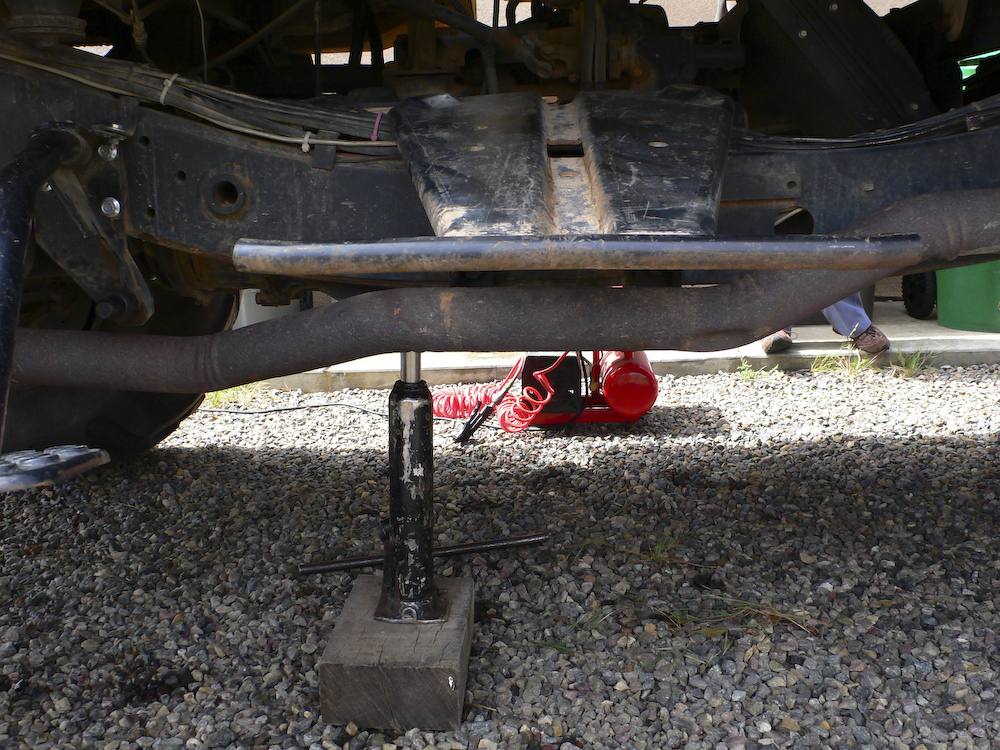
I sat there and talked to myself for what seemed like most of the afternoon and I finally came up with a possible plan. The plan was simple but unlikely to work. That said, I had no Plan B, so making a choice was easy. The plan was to use wooden blocks and one of my heavy lift hydraulic jacks to reposition the transmission into the correct location to allow selecting forward gears. Then, we would use 2 heavy duty ratchet straps to hold the transmission assembly in place. To assist in keeping it in place, we would re-install the sheared bolts to help act as pins to keep the transmission from moving around during travel. It took us several hours to get the fix in place, but we did it. I tightened those straps until they were so tight that I got "C sharp" when you plucked them!
We loaded our stuff and attempted to head down the hill.
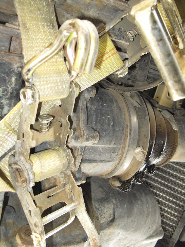
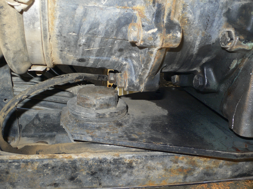
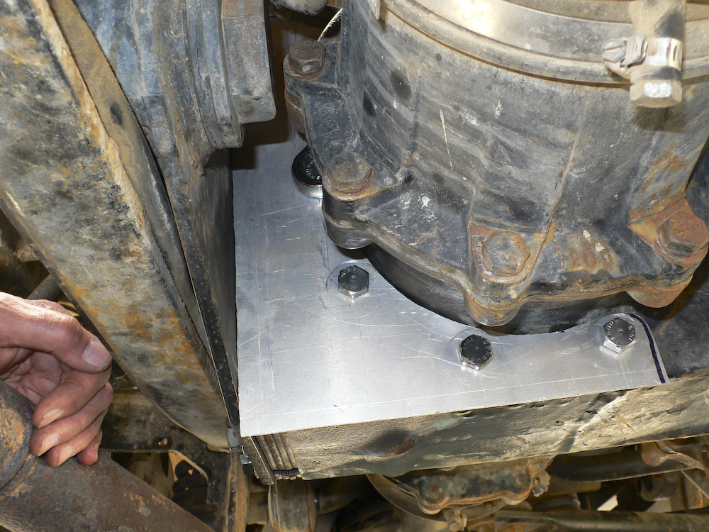
A view from the underside of the ratchet strap repair job.
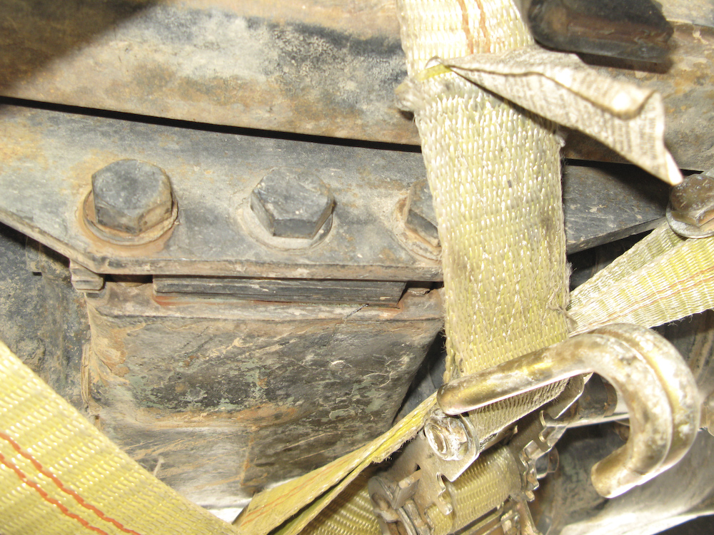
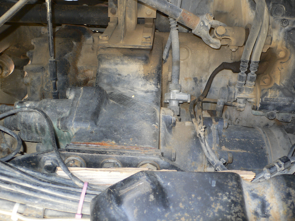
Another
view of the ratchet straps holding the transmission in
place. Look carefully and you can see a crack in the casting
coming from the right-most bolt to the edge. This baby is
barely holding on!! Also, you can see the shim stack
between the frame rail and the tranny. I think as the
bolts came loose, the stack of
shims allowed the
bolts to bend, then finally fatigue and break. A
solid machined block would not have allowed that to happen as
easily.
We are ready to roll down the hill. Literally. This hill is very, very steep and once I was fully committed, I discovered that the truck would not stay in forward gear. In the end, I had to come down the grade with no engine braking to slow the descent. I used only the normal brakes and crept at the slowest possible speed.
Once we got to the bottom of the canyon, I could not get the truck into forward gear at all. And, we had a very steep up grade to attack to get back to the cowboy shack. Once we got to the bottom, we pulled the spare tire again (which is no small amount of work given the size of the tire) to gain access to the transmission. Not surprisingly, the whole assembly had shifted during the steep down grade to the canyon floor. We hemmed and hawed and huffed and puffed and finally got partial engagement of the forward gears in compound low. Anything was better than nothing, so we loaded the spare tire again and took off up the grade in compound low which was about 1 mph (maybe less). We had sufficient fuel and water, so assuming we could keep the truck in gear, we COULD get out, although it may take several days. At this point, that seemed good to me, so off we went.
After we got past the cowboy shack and the road got more level, the whole assembly shifted closer to its normal operating position. While the rig would not fully stay in gear and popped out every time I let off the throttle, it was running. And, later, I discovered that it had moved sufficiently to allow me to get out of compound low and into normal street gear. This was good as we had 50 miles of trail to go. I still could not hit any gear where the lever had to be aft. So, I had 1st, 3rd, 5th and 7th gears but none of the others. But, that was sufficient. It is a big jump from 3rd to 5th, but we struggled through. Later I discovered that being in 4WD exacerbated the issue, so after we did not need it any more, we were 2WD the whole way back. Ugly, but we were mobile. As we got more confident in the fix, and the transmission assembly continued to shift more toward its normal operating position, we actually started discussing finding a camp site and staying the night. I was really beat. The combination of the heat, the stress, the exertion made a nice meal sound pretty inviting. But after much discussion and the devil on my shoulder pleading to stop for the night, we both concluded that it would be pressing our luck beyond any reasonable bound. So, we kept rolling with the plan being to get to Page, get a motel, get a shower, meal and a good night's rest and attack the issues tomorrow.
We made it the 800 miles back to San Diego without incident, but it was tense. When we got back, my buddy Kai and I attacked the issue in a more convenient venue.
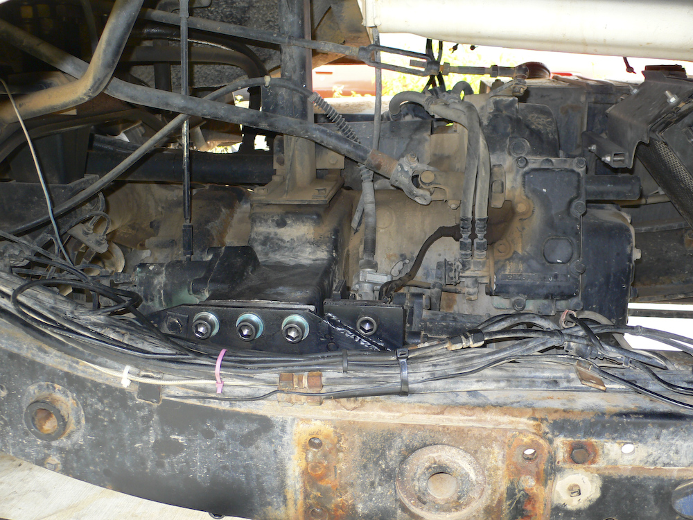
The action here is to get the bolt stubs that are broken off in the transmission case out and get them replaced with new bolts. But first, we have to remove the spare tire carrier, seen here in the center of the photo. One of the earlier owners was kind enough to weld the carrier onto the frame. Well, there was a bead where a weld WOULD have gone if he had known what the hell he was doing.
The ratchet straps that held the transmission in place were removed. The straps ablated the housing and you can see where they were in the photo above.
The spare tire frame came out easily. Once the last bolt was removed, the thing fell in our laps as the welds were SO shitty they did not even penetrate the frame. Our luck, I guess. I wonder what else that owner "fixed".
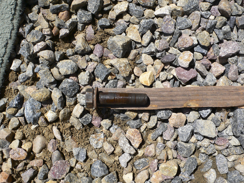
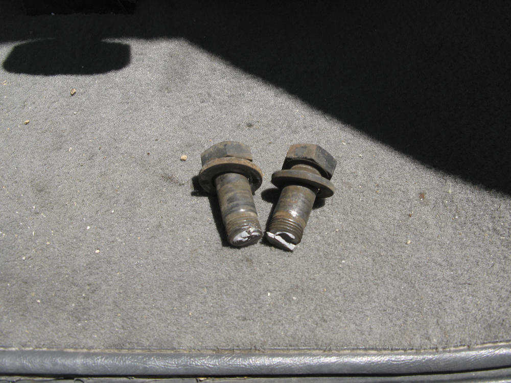
One of the bolts that came out from the bottom of the transmission mount was bent. If you look carefully, you can see the bend. These are metric 16mm 12.9 hardened bolts.
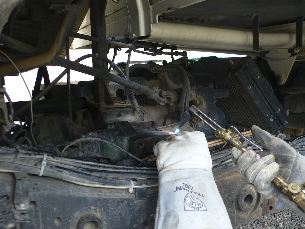
The transmission was jacked up to allow drilling into the bolt stubs to insert an easy-out screw extractor.
The first 2 bolts came out easy. Basically, Kai drilled into them with a left hand bit and they just spun out. The last bolt, however, was another story.
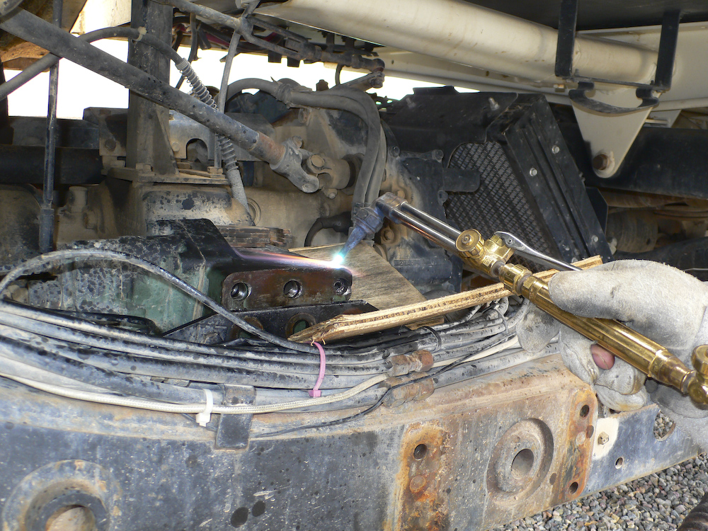
Try number 1. This fellow is tightly in there and will not come out. Kai thinks that applying the torch to heat the casing may break the hold that the rust has on the bolt fragment. We turned the easy-out so hard that we were fearful of breaking it, so we turned to the torch.
Try number 2, no good. Heat it again, apply mucho penetrating lubricant and hit it with the air hammer.
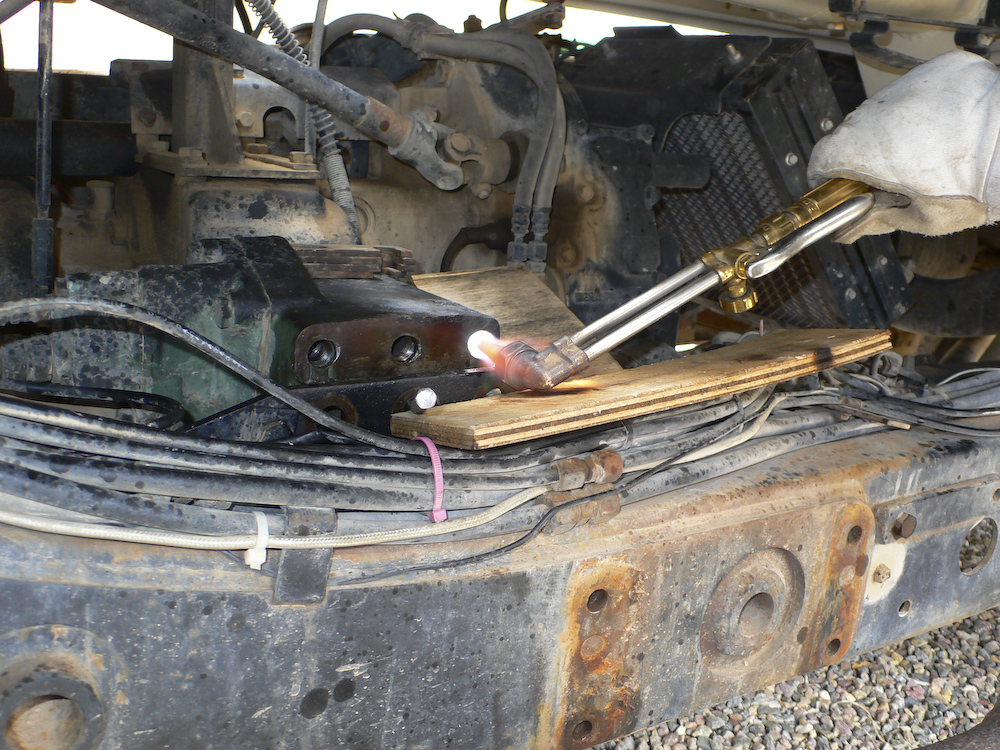
Still no good. Ok, no more Mr. Nice Guy. Now Kai gets fully medieval on that bolt. It did come out after this treatment. But there was much drilling, pounding and cussing involved in getting this bolt out. I am glad that I did not attempt this in the parking lot of the True Value Hardware in Page, AZ as I would have surely failed. Plus, getting the correct bolt would turn out to be an issue, taking a special order and several days for delivery.
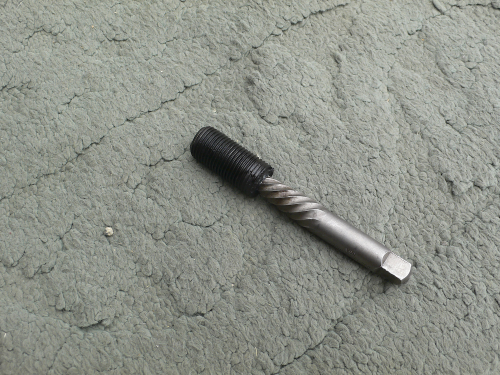
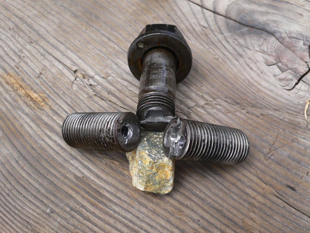
A souvenir.
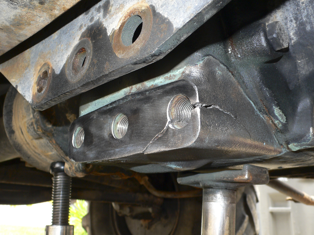
So, here is the bad news. This is a big crack. And, even if we could weld it, it would likely never handle the stress that is required. Some other alternative will be required.
The crack is both big and deep. On closer inspection, it seems that the crack has been there for some time and may have started separate to this event. Clearly, this did not make it any better. The bolt hole in this corner of the case, is, in my opinion, not salvageable, thus requiring another approach. A number of methods of splinting the case were discussed, and in the end, all but one was discarded.
Progress Update on 20080529
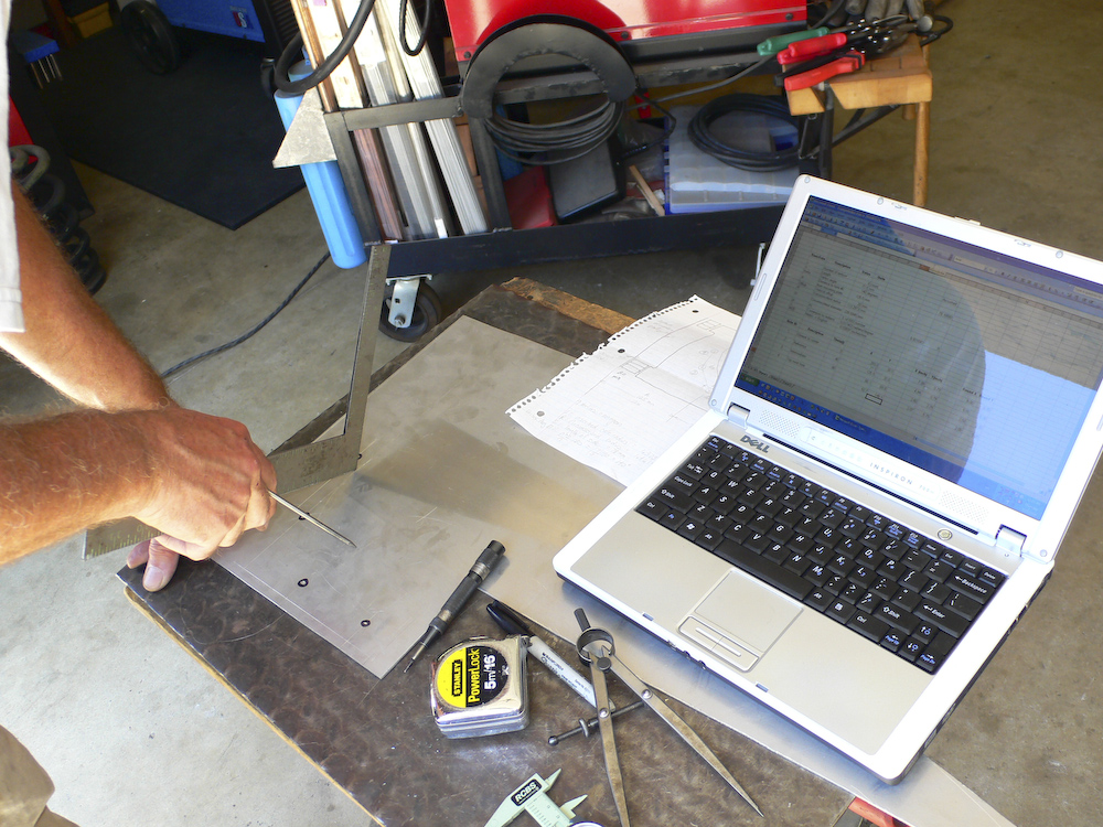
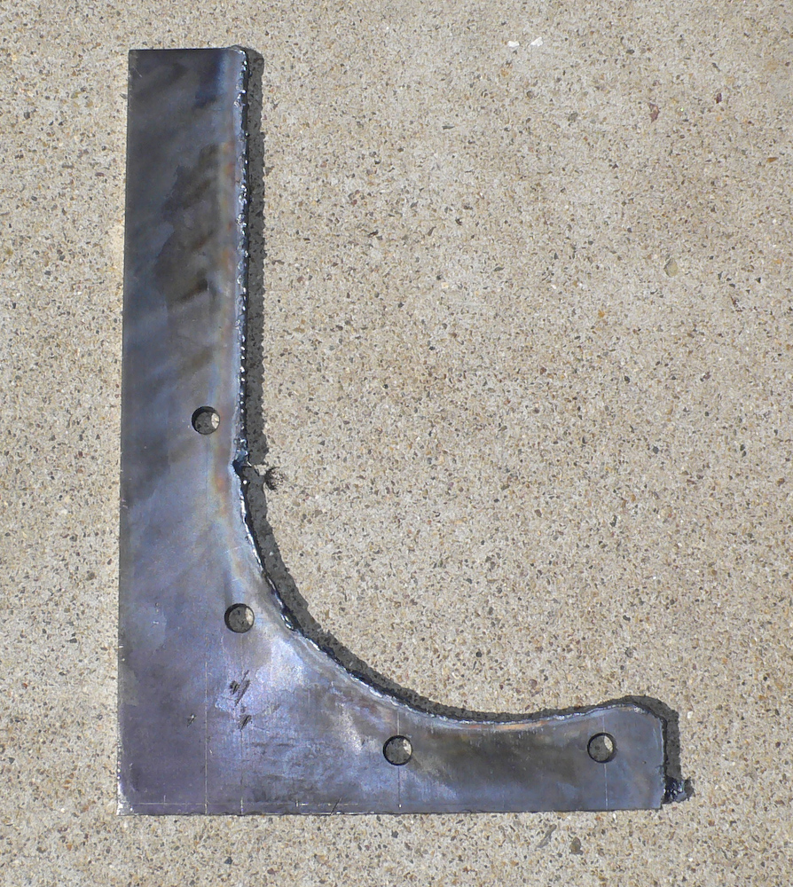
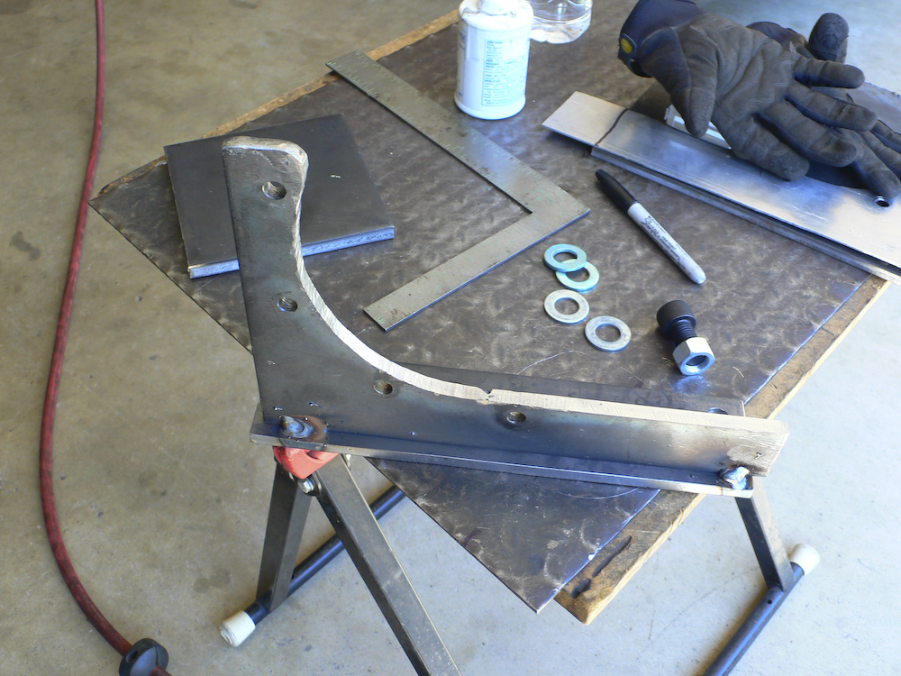
I had managed to connect with Mark Mitchell and we had worked out a date to start the effort to finalize the design of the splint. First, I visited him and we discussed in detail the plan and all the possible considerations. Then, we planned the work. The following day, we started in earnest. The photos below were shot during the design, fabrication and installation of the splint.
The plan was to make a crescent-shaped bracket and have that bracket bolt onto the aft torque tube housing. These bolts are seen on the right of the photo, with 3 bolts visible. These are M10x40mm class 10.9 bolts with hex heads.
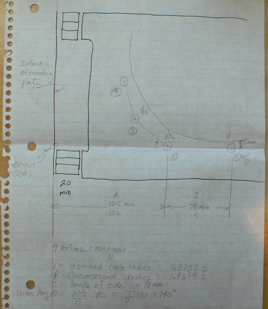
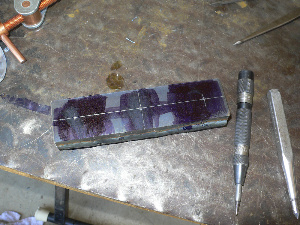
Here is a side view of the notebook page on the layout. Sadly, the case was a 9 bolt pattern which required me to exhume my CRC Math Tables to get the formula for a 9-sided regular polygon (called a nonagon). Once you assume the orientation of 2 of the holes, which in this case were horizontal, then the balance of the geometry is solely determined by the length of a side. So, making that measurement would be critical to making the bracket without having to ream and re-ream the holes. For the splint to be effective, it will have to be tight against the housing and to have all the bracket bolts tight with little or no play to accommodate the shear load due to the missing mounting bolt. Since the housing was cracked, I elected to not use the hole at all. The only real consideration was insuring that the combined strength of the 4 bolts is equal or more than the strength of the missing bolt. We were lucky that it was. Metric bolts are tagged with "classes" on the head of the bolt, in this case class 10.9. This class corresponds to the strength of the bolt. More specifically, it lists the failure strength and the point at which the bolt starts to stretch. These values are encoded in the head stamp. Class 10.9 means 100 N/mm^2 stress to failure point with a stretch point of 90% of the failure value. So, since the strength is expressed in units of force per area, if we know the area, then we can assess the overall force at the time the bolt fails. The strength of the missing 16mm bolt is PI* (16/2)^2, the old pi-R-squared formula, times the class number 12. In this case, the value is 2411 Newtons. For 4 bolts of the splint, the value is 3141 Newtons: score!
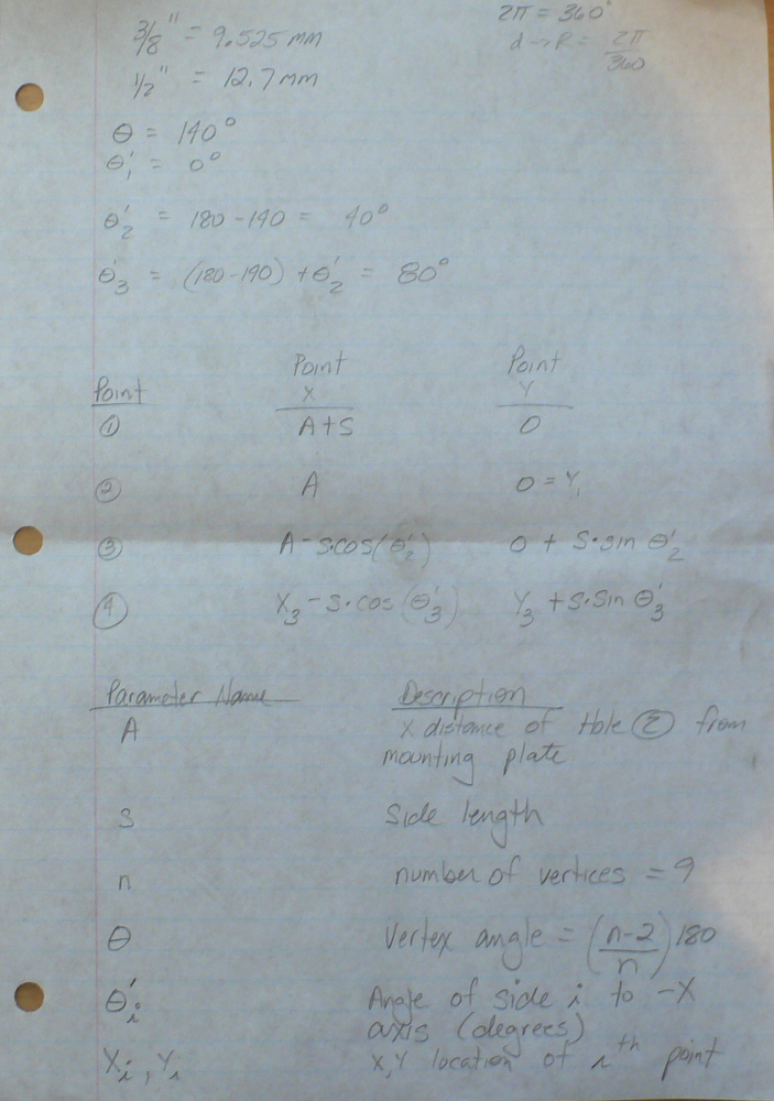
This whole thing was a good news, bad news. The good news was that the equations that determine the hole locations are easy to compute. The bad news is that the final results are critically dependent on the correct measurement of the inter-hole spacing (length of a side). Measuring accurately upside down is just plain hard. I had expected this and created a spread sheet that would allow me to enter parameters easily and then it would tell me the final locations. That was good, because our initial measurements were quite inaccurate, resulting in the need re-measure many times. The old adage: "Measure twice; cut once" was really "Measure 20 times, layout once".
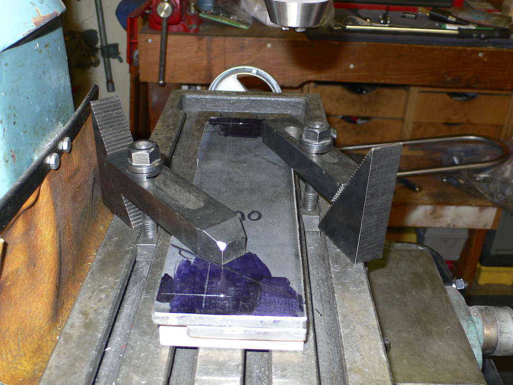
We used our initial measurements to layout the bolt hole locations in some scrap aluminum that we would use as a template. But, the holes we drilled did not come out round, so our estimates were not that good. The work piece had shifted during the drilling process.
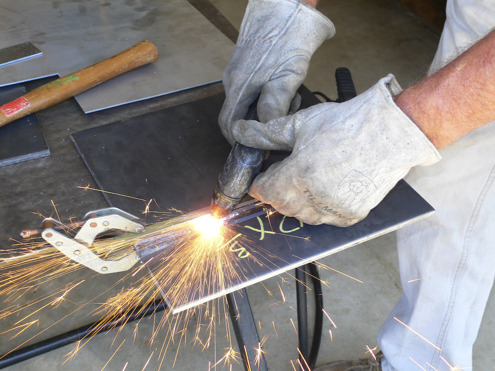
I removed the main bolts and Mark cut some plate with his plasma torch.
The
holes are empty now, you can see where the plate will go. And you can see the
shim stack and the cracked corner of the case.
The template went in well, but since the holes were not round, we had no confidence in the actual location of the bolts. In the end, we decided to re-layout the holes on the actual steel plate from scratch and ignore the template. The fact that it fit was a necessary condition, but not a sufficient condition for our success. In the end, this turned out to be a good decision.
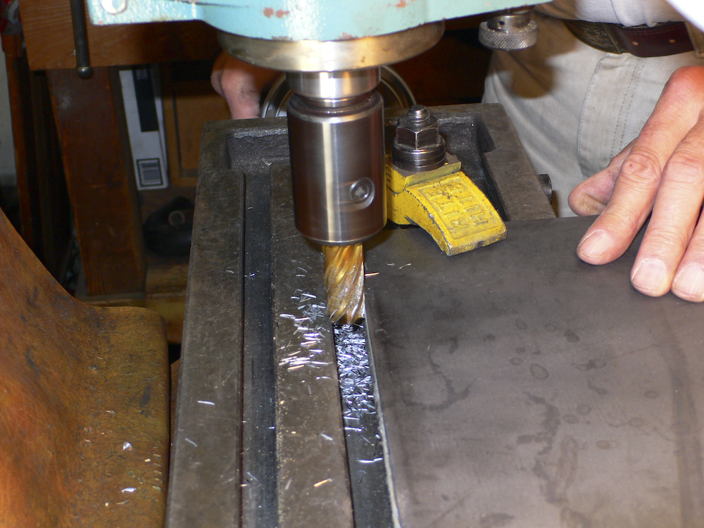
To get accurate locations, you have to have an edge that is straight. Here, Mark mills the edge of the plate to get a flat, straight side for the layout of the holes.
The layout went well and the next step was to drill the holes and then mark the curved surface. Once the curve was marked, I took Mark's cutting torch and cut the metal. Except for when the hose got caught on something and then jerked when it broke free, (thus the big hole about 1/2 way up), the cut went well.
Yowzir. We hit this first time with no reaming required. We did find, however, that the inside curve needed to be radiused a bit as it was hitting the fillet on the casting. To do this, Mark put it in the mill and guided the curve by hand. Once re-installed, it fit like a glove. And the edge of the bracket was parallel to the mounting plate on the frame. The old shim stack is visible at the lower left of the photo. As a side note, due to the extra thickness of the bracket, I had to get longer bolts as well. These bolts JUST fit between the limits of the existing casting. But, to perform the installation, the bolts have to be inserted into the bracket before the bracket is moved into position -- otherwise, it will not fit.
Now on to the mounting plate and flange. These parts needed to share 2 holes in common and it was critical that they were perfectly aligned. So, the parts were clamped in the mill and gang-drilled.
Crescent plate was then welded to the flange.
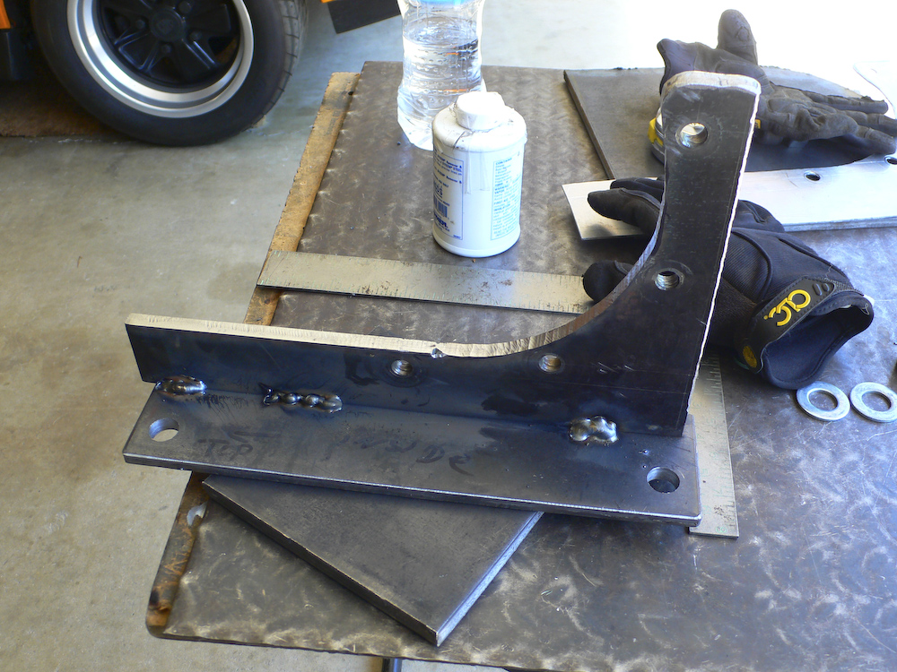
The tacks were complete, then the frame was hard-welded together.
Mark mounted the other plate onto the frame and welded it tight with his MIG welder. Then the assembly was sprayed with some paint.
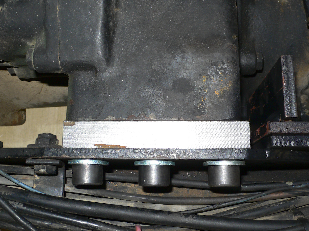
Two half inch plates were welded together into a stack to make the 20mm shim block that will replace the stack of shims that have been on the truck since I bought it 12 years ago. The hole positions were laid out and the holes were drilled. Then, the stack was cut to a thickness of 20 mm with the mill.
This could not have come out any snugger. There was a very small warp of the angle of the flange with the bracket, but it did not impact the ability to assemble the unit. The old shim stack is visible at the lower left of the photo.
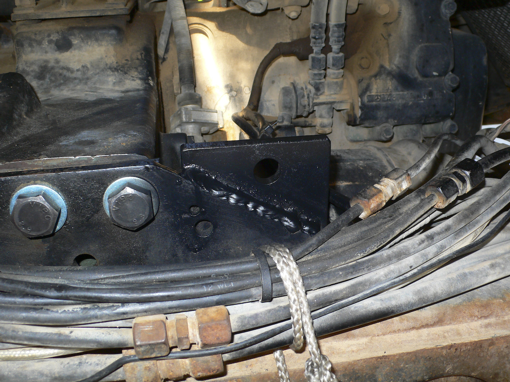
The last act was to replace the wimpy 8.8 bolts with factory-spec 12.9 socket head cap screws and insert the shim blocks. This was a tight fit, but it did not require reaming the holes - they were correct as measured and drilled. The shim block is the silver part. The splint is visible in the lower right of the photo.
The final view, fully assembled and ready to drive.
This
went surprisingly well. Usually, you can never measure very
accurately, and measuring upside down on a curve would be
hopeless for me. Special thanks to Kai and Mark for their
assistance, without which this would not have been possible.
The only item remaining is to drain and replace the tranny
fluid for inspection and to insure that any metal fragments
from abuse during the failure are removed.
It should be noted
that the splint
has held up well. Perhaps not as well as the
original setup, but that would have required that the
shim stack be
replaced with
a single
machined block and the use of the correct hardened
bolts. But, the net-net is that this problem
is conclusively solved.
Clutch
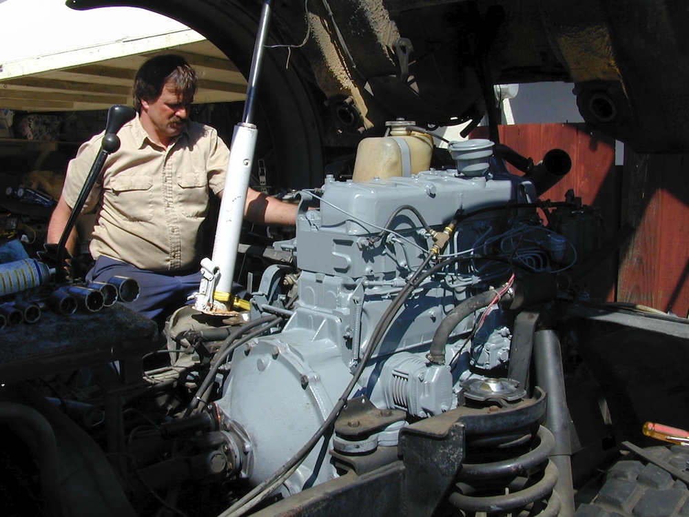
Of all the subsystems in the mog, we had the least trouble
with the clutch. Now, we did take it out and rebuild it
when the motor fried, but was not showing
problems. But, since we had it apart already and
the rebuild was cheap, it seemed like the thing to do.
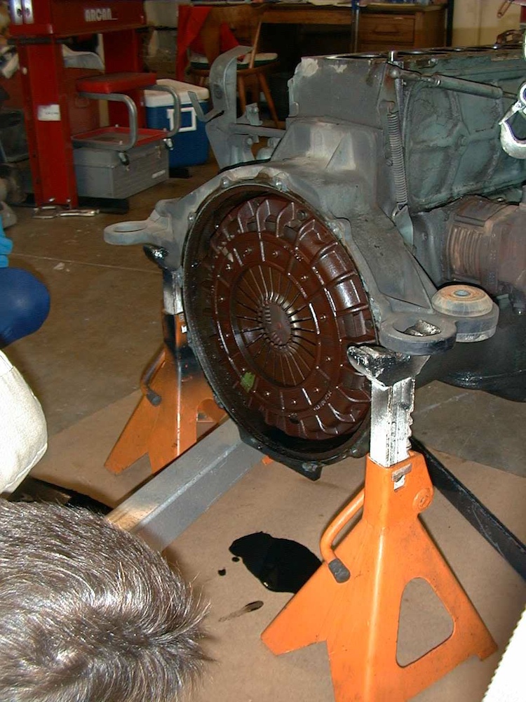
The clutch assembly
behind the bell housing.
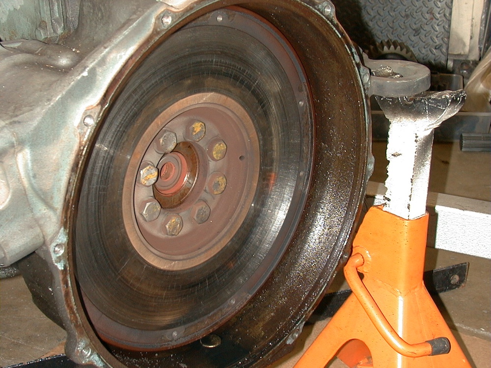
The face of the
flywheel showed some stress cracks.
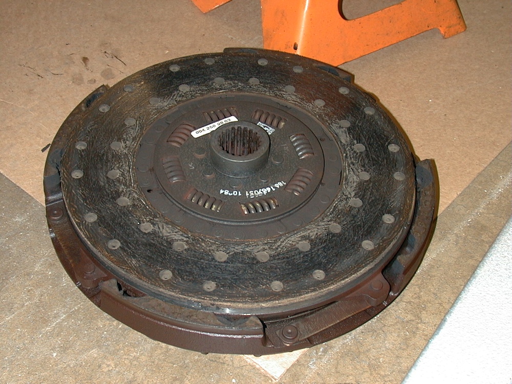
Old clutch before rebuild.
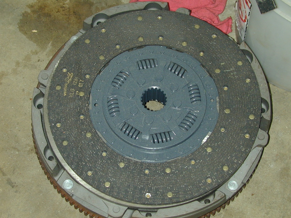
clutch after
rebuild.
The bell housing
is shown in the photo above with the output prop shaft.
The hydraulic portion of the clutch is a
separate story. We had a failure that stranded us for
4 days waiting for parts. The problem was simple: old
rubber. The flex hose for the clutch line gave out
after 30 years; plain and simple old age. There are 4
main components to the hydraulic portion of the mog clutch:
master cylinder; hardline; flex line; slave
cylinder. The only component that we never had fail
was the hard line, each of the others failed at least once
over the years. See those photos later on this page.
The easy solution for old rubber is just
replace it all proactively. Recalling the lingering
issues I had on my 1300, this is exactly what I did on my
1017A. Need it or not, it is 20+ years old so it is
getting replaced. You may want to consider the same
process, at least on the clutch as the components are not
that expensive nor that hard to get access to. And, it
will save you mucho hassle.
The one maintenance item you really MUST do is to change the clutch fluid every year. The fluid is DOT 3 brake fluid and just like in your brakes, it accumulated moisture. The slave cylinder will take the brunt of the rust damage, but it is easily prevented by changing the fluid. The process is the same as the brakes - depress, open vent, close vent, release. Be sure to keep the reservoir full to prevent the system from sucking air. Air in the lines will give you a mushy pedal or no clutch operation at all.
We did have a flex line failure on the return portion of our trip to the Arctic Ocean. On the downgrade into Wenatchee, WA my clutch pedal started going to the floor and not returning during shifts. Since this happened many years ago, I was prepared to refurbish the slave cylinder portion of the hydraulic clutch. So, we went directly to the auto parts store and got a big selection of metric O rings expecting to replace the O ring and be on our way. After we bought the parts, we got back in the truck and the pedal went to the floor and that was that. We spent 6 hours in the parking lot attempting to effect a repair and did finally get the truck functional enough to get across the street to a motel.
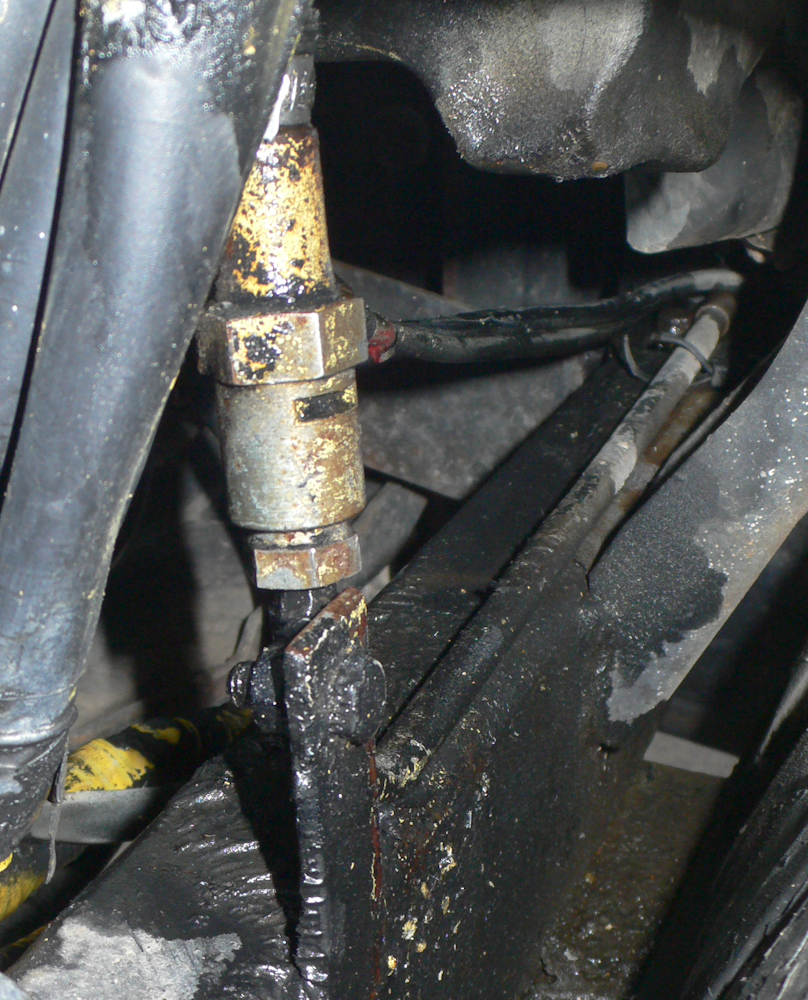
The issue was not the master or slave cylinder, but rather a flex hose where the cab meets the frame. The balance of the plumbing was hard lines, but to allow the cab to tilt for service, a flex line was needed. That line, after 30 years, gave out. This is a high pressure line, so getting the right kind of hose was hard. I managed to get one end of the line undone and insert a hose barb and hose clamps, but the line was still leaking.
The other end of the flex line was deep inside and was very hard to reach. In the end, I had to remove the fender and a number of clamps that held the hard line to the body to gain access to the other fitting to allow me to remove the flex line. When I did remove it, I realized that the hose was totally shot without any chance of repair. I had already ordered a replacement, but it took several days for the part to arrive.
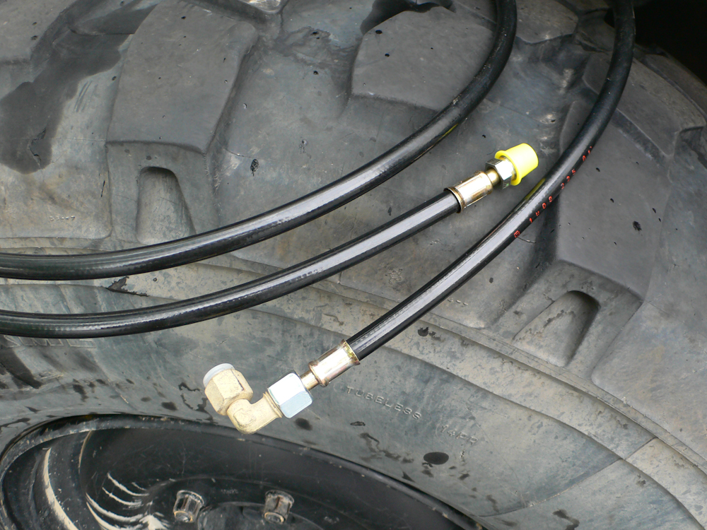
When the part arrived, we were ready. The part showed up at noon and we had it fully installed by 1400. Above, the new line can be seen. The new line is all flex line and should last for at least another 20 years.
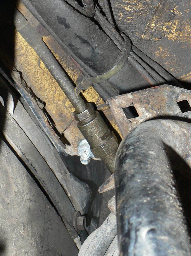
The old hard line comes through the fire wall right in the center of the photo.
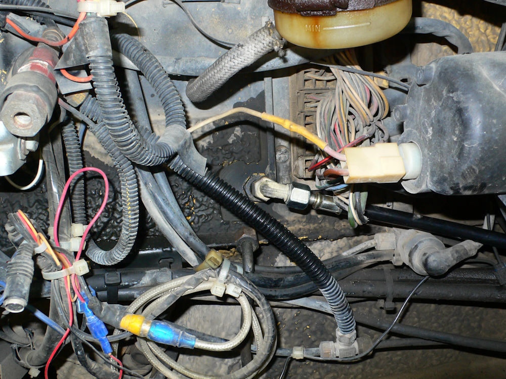
The replacement line has an angle fitting at the firewall that connects to the flex line.
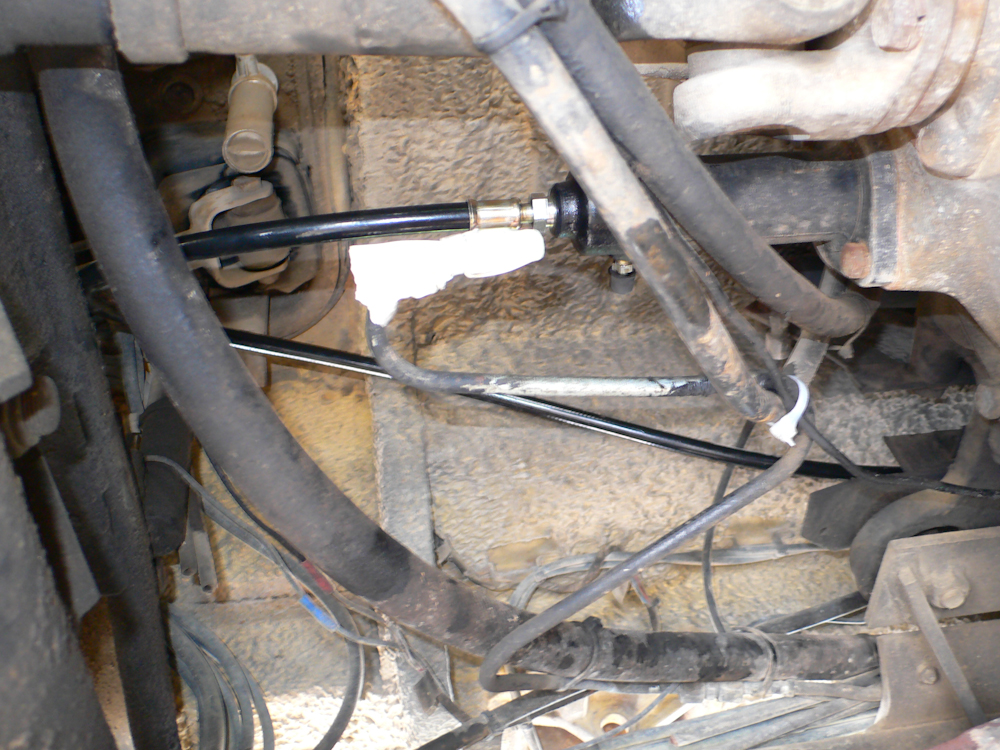
This shot was looking up from underneath the slave cylinder. We cut a finger off a rubber glove to keep dirt out of the old hard line in case we wanted to use it again. I doubt we will but at least we have that alternative open to us.
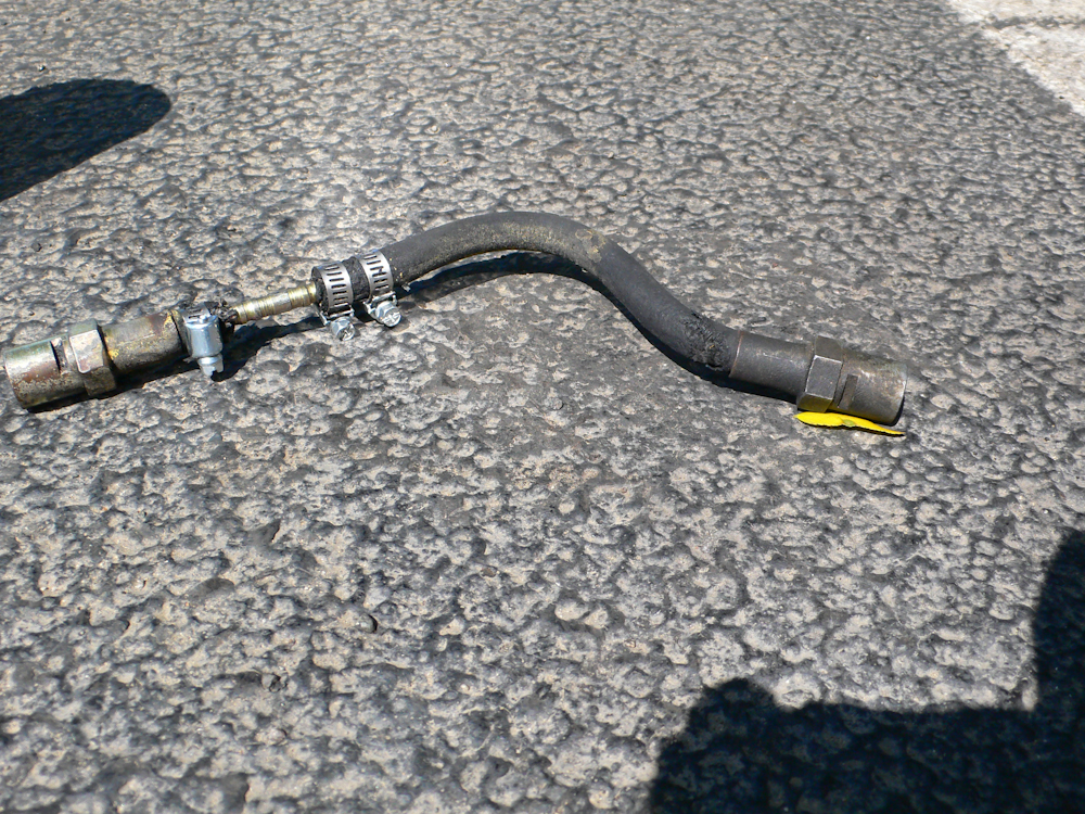
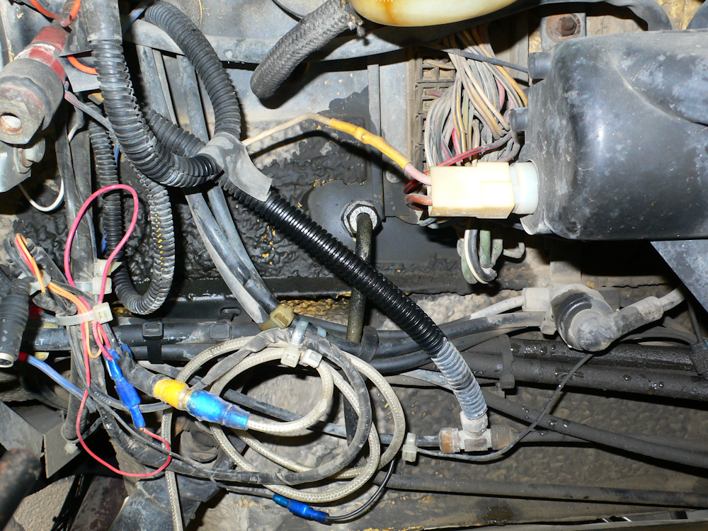
The old flex line with the ad hoc repair. What I could not see while it was installed was that the other end of the hose was violated as well.
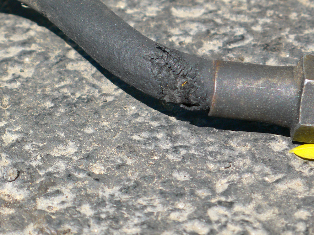
The real reason that the
fix would not work - the hose was broken in more than one
location, so no matter what, I was destined to replace the
entire line. Of course, that was the correct solution for
many reasons. So, after four days in a motel in Wenatchee,
WA, we had
the problem
solved.
The mechanical clutch in the SBU mogs is quiet reliable. They are not that hard to get to, particularly if the motor is removed, so if you tilt the cab for any reason, you may want to consider removing the bell housing and doing an inspection and rebuild. From there you should be good for 10 years or so with no issues.
I
believe that if you change your clutch fluid
on a regular schedule, you will not have
any issues at all, particularly if
you are starting with a new master and slave cylinder
and have a new flex line.
Quick Links:
Zen and Art Home
Disclaimer
Errata Parts and
Parts Vendors Truck Sales
Service
and Repairs
Engine Fuel Hydraulics Radiator and
Cooling Air
System Brakes
Wheels Tires Electrical
and Batteries